1. General
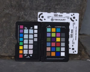
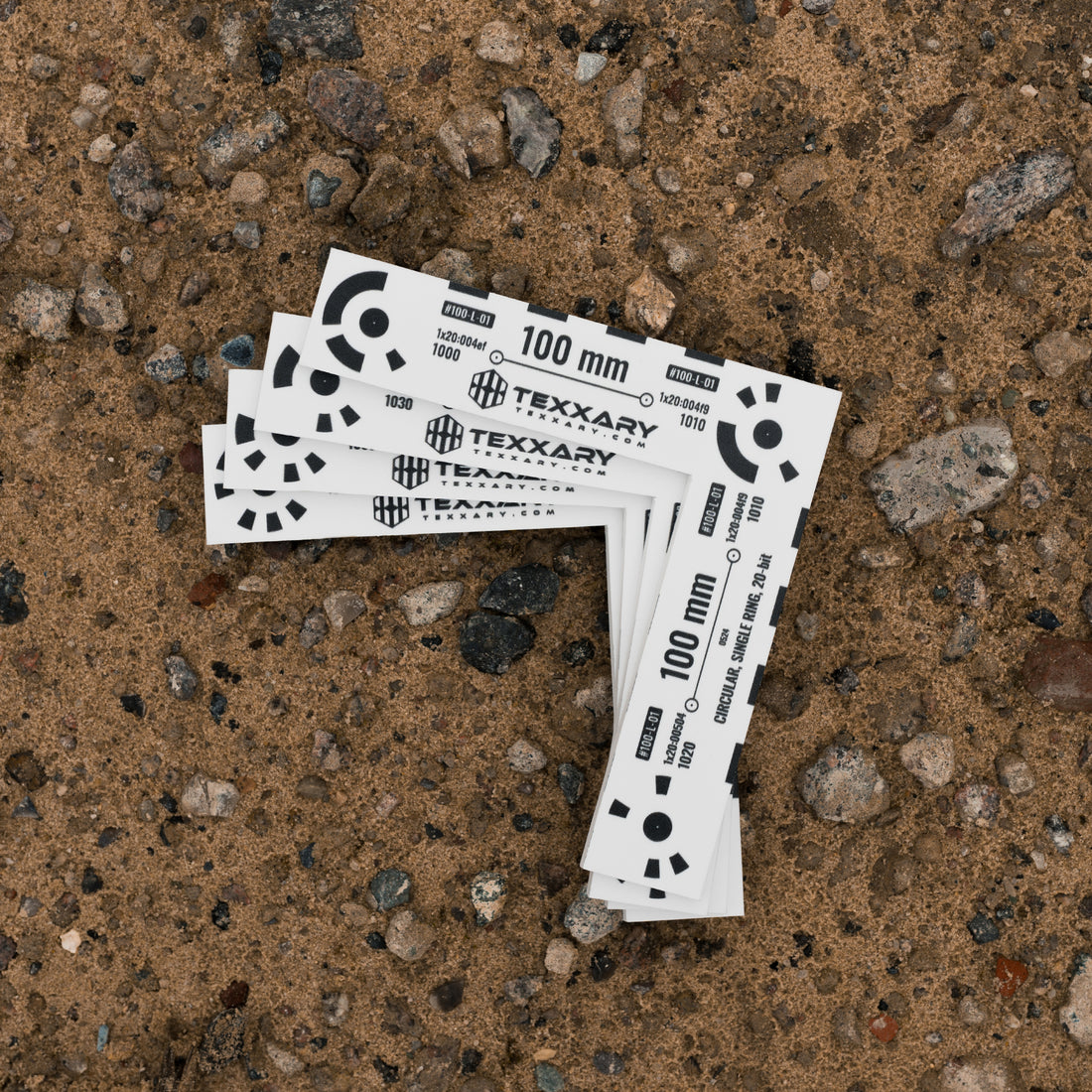
Scale bars with coded targets or april tags are used in advanced 3D scanning and photogrammetry to ensure that the 3D scans are correctly scaled and oriented. These targets have known distances, which helps the software align everything quickly and accurately. Most of the major scanning software can automatically detect these targets and set the scale by themselves. This is a big advantage, especially for automated processes using the command line tools of scanning software. It makes the workflow faster and more consistent, which is very helpful in professional settings where tons of scans have to be processed automaticaly.
2. Scanning
The scale bar needs to be included in the scan of the asset. Make sure that the scale bar is not moving during scanning. It’s important to take enough photos of the coded targets, making sure each target appears in at least four photos. The more photos include the targets, the better. This helps in making the detection more precise and reduces the chance of errors in detection. Essentially, having more photos covering each target leads to a more accurate and reliable alignment process.

3. Software
3.1 Reality Capture
The target detection and scaling is usually being made after the alignment or the model creation. It can either being made manually or automatically using the CLI tool of reality capture.
3.1.1 Manually
To start the target detection go to the “ALIGNMENT” tab and on the very left in the “Optional” group click “Detect Markers”. In the options make sure to put the “Markers type” to “Circular, single ring, 20-bit” when using Texxary Scale Bars. The “Required measurments” is the minimum number of photos that is required for the detection of one target. Usually it’s fine using 3. A higher number ensures a better precision but it reuires that enough photos are being shot. Click “Detect” to automatically detect the targets.

When the target detection is done, the control points will be listed in the “Control points” group in the “1Ds” view. When expanding a point, it will list all the images containing the found point. On the right it will show an “error value” measured in pixels. If it has an error of 4px, it means the detection is 4 pixels inaccurate. If necessary, delete all detections that are red and have a high detection error value.

To assign the distance easily download and use the correct distance definition file below. It’s a simple text file that contains the name of the distance, the two points and the distance in meters. It looks like this: 10cm_Distance,1×20:00164,1×20:0016e,0.10
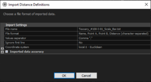
Go to the “WORKFLOW” tab and in the “Import & Metadata” group click “Distance Definition” and choose the correct .txt file. In the following window, make sure that “File format” is set to “Name, Point A, Point B, Distance (Character seperated)”, “Value seperator” should be set to “,” and “Ignore first line” should be “No”. Click “OK” to open the file.

Make sure to download and use the correct file based on the number of your scale bar (for example “100-I-01”). It should then use the correct points and assign the correct distance to it.
4. Distance Files
4.2 I-Bars (2 targets)
100-I-01 | 100-I-02 | 100-I-03 | 100-I-04
Texxary_ScaleBars_I_CodedTargets_DistanceConfig.zip (1KB)4.2 L-Bars (3 targets)
100-L-01 | 100-L-02 | 100-L-03 | 100-L-04
Texxary_ScaleBars_L_CodedTargets_DistanceConfig.zip (1KB)
